AI Face Upgrade

AI Face Upgrade — independent reviews, comparisons, pricing and step-by-step guides on Aizhi.

  • Stencil buffer

    Stencil buffer

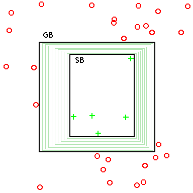
    A stencil buffer is an extra data buffer, in addition to the color buffer and Z-buffer, found on modern graphics hardware. The buffer is per pixel and works on integer values, usually with a depth of one byte per pixel. The Z-buffer and stencil buffer often share the same area in the RAM of the graphics hardware. In the simplest case, the stencil buffer is used to limit the area of rendering (stenciling). More advanced usage of the stencil buffer makes use of the strong connection between the Z-buffer and the stencil buffer in the rendering pipeline. For example, stencil values can be automatically increased/decreased for every pixel that fails or passes the depth test. The simple combination of depth test and stencil modifiers make a vast number of effects possible (such as stencil shadow volumes, Two-Sided Stencil, compositing, decaling, dissolves, fades, swipes, silhouettes, outline drawing, or highlighting of intersections between complex primitives) though they often require several rendering passes and, therefore, can put a heavy load on the graphics hardware. The most typical application is still to add shadows to 3D applications. It is also used for planar reflections. Other rendering techniques, such as portal rendering, use the stencil buffer in other ways; for example, it can be used to find the area of the screen obscured by a portal and re-render those pixels correctly. The stencil buffer and its modifiers can be accessed in computer graphics by using APIs like OpenGL, Direct3D, Vulkan or Metal. == Architecture == The stencil buffer typically shares the same memory space as the Z-buffer, and typically the ratio is 24 bits for Z-buffer + 8 bits for stencil buffer or, in the past, 15 bits for Z-buffer + 1 bit for stencil buffer. Another variant is 4 + 24, where 28 of the 32 bits are used and 4 ignored. Stencil and Z-buffers are part of the frame buffer, coupled to the color buffer. The first chip available to a wider market was 3Dlabs' Permedia II, which supported a one-bit stencil buffer. The bits allocated to the stencil buffer can be used to represent numerical values in the range [0, 2n-1], and also as a Boolean matrix (n is the number of allocated bits), each of which may be used to control the particular part of the scene. Any combination of these two ways of using the available memory is also possible. == Stencil test == Stencil test or stenciling is among the operations on the pixels/fragments (Per-pixel operations), located after the alpha test, and before the depth test. The stencil test ensures undesired pixels do not reach the depth test. This saves processing time for the scene. Similarly, the alpha test can prevent corresponding pixels to reach the stencil test. The test itself is carried out over the stencil buffer to some value in it, or altered or used it, and carried out through the so-called stencil function and stencil operations. The stencil function is a function by which the stencil value of a certain pixel is compared to a given reference value. If this comparison is logically true, the stencil test passes. Otherwise not. In doing so, the possible reaction caused by the result of comparing three different state-depth and stencil buffer: Stencil test is not passed Stencil test is passed but not the depth test Both tests are passed (or stencil test is passed, and the depth is not enabled) For each of these cases, different operations can be set over the examined pixel. In the OpenGL stencil functions, the reference value and mask, respectively, define the function glStencilFunc. In Direct3D each of these components is adjusted individually using methods SetRenderState devices currently in control. This method expects two parameters, the first of which is a condition that is set and the other its value. In the order that was used above, these conditions are called D3DRS_STENCILFUNC, D3DRS_STENCILREF, and D3DRS_STENCILMASK. Stencil operations in OpenGL adjust glStencilOp function that expects three values. In Direct3D, again, each state sets a specific method SetRenderState. The three states that can be assigned to surgery are called D3DRS_STENCILFAIL, D3DRENDERSTATE_STENCILZFAIL, and D3DRENDERSTATE_STENCILPASS. == Z-fighting == Due to the lack of precision in the Z-buffer, coplanar polygons that are short-range, or overlapping, can be portrayed as a single plane with a multitude of irregular cross-sections. These sections can vary depending on the camera position and other parameters and are rapidly changing. This is called Z-fighting. There exist multiple solutions to this issue: - Bring the far plane closer to restrict the scene's depth, thus increasing the accuracy of the Z-buffer, or reducing the distance at which objects are visible in the scene. - Increase the number of bits allocated to the Z-buffer, which is possible at the expense of memory for the stencil buffer. - Move polygons farther apart from one another, which restricts the possibilities for the artist to create an elaborate scene. All of these approaches to the problem can only reduce the likelihood that the polygons will experience Z-fighting, and do not guarantee a definitive solution in the general case. A solution that includes the stencil buffer is based on the knowledge of which polygon should be in front of the others. The silhouette of the front polygon is drawn into the stencil buffer. After that, the rest of the scene can be rendered only where the silhouette is negative, and so will not clash with the front polygon. == Shadow volume == Shadow volume is a technique used in 3D computer graphics to add shadows to a rendered scene. They were first proposed by Frank Crow in 1977 as the geometry describing the 3D shape of the region occluded from a light source. A shadow volume divides the virtual world in two: areas that are in shadow and areas that are not. The stencil buffer implementation of shadow volumes is generally considered among the most practical general-purpose real-time shadowing techniques for use on modern 3D graphics hardware. It has been popularised by the video game Doom 3, and a particular variation of the technique used in this game has become known as Carmack's Reverse. == Reflections == Reflection of a scene is drawn as the scene itself transformed and reflected relative to the "mirror" plane, which requires multiple render passes and using of stencil buffer to restrict areas where the current render pass works: Draw the scene excluding mirror areas – for each mirror lock the Z-buffer and color buffer Render visible part of the mirror Depth test is set up so that each pixel is passed to enter the maximum value and always passes for each mirror: Depth test is set so that it passes only if the distance of a pixel is less than the current (default behavior) The matrix transformation is changed to reflect the scene relative to the mirror plane Unlock the Z-buffer and color buffer Draw the scene, but only the part of it that lies between the mirror plane and the camera. In other words, a mirror plane is also a clipping plane Again locks color buffer, depth test is set so that it always passes, reset stencil for the next mirror. == Planar Shadows == While drawing a plane of shadows, there are two dominant problems: The first concerns the problem of deep struggle in case the flat geometry is not awarded on the part covered with the shadow of shadows and outside. See the section that relates to this. Another problem relates to the extent of the shadows outside the area where the plane there. Another problem, which may or may not appear, depending on the technique, the design of more polygons in one part of the shadow, resulting in darker and lighter parts of the same shade. All three problems can be solved geometrically, but because of the possibility that hardware acceleration is directly used, it is a far more elegant implementation using the stencil buffer: 1. Enable lights and the lights 2. Draw a scene without any polygon that should be projected shadows 3. Draw all polygons which should be projected shadows, but without lights. In doing so, the stencil buffer, the pixel of each polygon to be assigned to a specific value for the ground to which they belong. The distance between these values should be at least two, because for each plane to be used two values for two states: in the shadows and bright. 4. Disable any global illumination (to ensure that the next steps will affect only individual selected light) For each plane: For each light: 1. Edit a stencil buffer and only the pixels that carry a specific value for the selected level. Increase the value of all the pixels that are projected objects between the date of a given level and bright. 2. Allow only selected light for him to draw level at which part of her specific value was not changed. == Spatial shadows == Stencil buffer implementation of spatial drawing shadows is any shadow of a geometric body that its volume includes part of the scene that is

    Read more →
  • Dynamic time warping

    Dynamic time warping

    In time series analysis, dynamic time warping (DTW) is an algorithm for measuring similarity between two temporal sequences, which may vary in speed. For instance, similarities in walking could be detected using DTW, even if one person was walking faster than the other, or if there were accelerations and decelerations during the course of an observation. DTW has been applied to temporal sequences of video, audio, and graphics data — indeed, any data that can be turned into a one-dimensional sequence can be analyzed with DTW. A well-known application has been automatic speech recognition, to cope with different speaking speeds. Other applications include speaker recognition and online signature recognition. It can also be used in partial shape matching applications. In general, DTW is a method that calculates an optimal match between two given sequences (e.g. time series) with certain restriction and rules: Every index from the first sequence must be matched with one or more indices from the other sequence, and vice versa The first index from the first sequence must be matched with the first index from the other sequence (but it does not have to be its only match) The last index from the first sequence must be matched with the last index from the other sequence (but it does not have to be its only match) The mapping of the indices from the first sequence to indices from the other sequence must be monotonically increasing, and vice versa, i.e. if j > i {\displaystyle j>i} are indices from the first sequence, then there must not be two indices l > k {\displaystyle l>k} in the other sequence, such that index i {\displaystyle i} is matched with index l {\displaystyle l} and index j {\displaystyle j} is matched with index k {\displaystyle k} , and vice versa We can plot each match between the sequences 1 : M {\displaystyle 1:M} and 1 : N {\displaystyle 1:N} as a path in a M × N {\displaystyle M\times N} matrix from ( 1 , 1 ) {\displaystyle (1,1)} to ( M , N ) {\displaystyle (M,N)} , such that each step is one of ( 0 , 1 ) , ( 1 , 0 ) , ( 1 , 1 ) {\displaystyle (0,1),(1,0),(1,1)} . In this formulation, we see that the number of possible matches is the Delannoy number. The optimal match is denoted by the match that satisfies all the restrictions and the rules and that has the minimal cost, where the cost is computed as the sum of absolute differences, for each matched pair of indices, between their values. The sequences are "warped" non-linearly in the time dimension to determine a measure of their similarity independent of certain non-linear variations in the time dimension. This sequence alignment method is often used in time series classification. Although DTW measures a distance-like quantity between two given sequences, it doesn't guarantee the triangle inequality to hold. In addition to a similarity measure between the two sequences (a so called "warping path" is produced), by warping according to this path the two signals may be aligned in time. The signal with an original set of points X(original), Y(original) is transformed to X(warped), Y(warped). This finds applications in genetic sequence and audio synchronisation. In a related technique sequences of varying speed may be averaged using this technique see the average sequence section. This is conceptually very similar to the Needleman–Wunsch algorithm. == Implementation == This example illustrates the implementation of the dynamic time warping algorithm when the two sequences s and t are strings of discrete symbols. For two symbols x and y, d ( x , y ) {\displaystyle d(x,y)} is a distance between the symbols, e.g., d ( x , y ) = | x − y | {\displaystyle d(x,y)=|x-y|} . int DTWDistance(s: array [1..n], t: array [1..m]) { DTW := array [0..n, 0..m] for i := 0 to n for j := 0 to m DTW[i, j] := infinity DTW[0, 0] := 0 for i := 1 to n for j := 1 to m cost := d(s[i], t[j]) DTW[i, j] := cost + minimum(DTW[i-1, j ], // insertion DTW[i , j-1], // deletion DTW[i-1, j-1]) // match return DTW[n, m] } where DTW[i, j] is the distance between s[1:i] and t[1:j] with the best alignment. We sometimes want to add a locality constraint. That is, we require that if s[i] is matched with t[j], then | i − j | {\displaystyle |i-j|} is no larger than w, a window parameter. We can easily modify the above algorithm to add a locality constraint (differences marked). However, the above given modification works only if | n − m | {\displaystyle |n-m|} is no larger than w, i.e. the end point is within the window length from diagonal. In order to make the algorithm work, the window parameter w must be adapted so that | n − m | ≤ w {\displaystyle |n-m|\leq w} (see the line marked with () in the code). int DTWDistance(s: array [1..n], t: array [1..m], w: int) { DTW := array [0..n, 0..m] w := max(w, abs(n-m)) // adapt window size () for i := 0 to n for j:= 0 to m DTW[i, j] := infinity DTW[0, 0] := 0 for i := 1 to n for j := max(1, i-w) to min(m, i+w) DTW[i, j] := 0 for i := 1 to n for j := max(1, i-w) to min(m, i+w) cost := d(s[i], t[j]) DTW[i, j] := cost + minimum(DTW[i-1, j ], // insertion DTW[i , j-1], // deletion DTW[i-1, j-1]) // match return DTW[n, m] } == Warping properties == The DTW algorithm produces a discrete matching between existing elements of one series to another. In other words, it does not allow time-scaling of segments within the sequence. Other methods allow continuous warping. For example, Correlation Optimized Warping (COW) divides the sequence into uniform segments that are scaled in time using linear interpolation, to produce the best matching warping. The segment scaling causes potential creation of new elements, by time-scaling segments either down or up, and thus produces a more sensitive warping than DTW's discrete matching of raw elements. == Complexity == The time complexity of the DTW algorithm is O ( N M ) {\displaystyle O(NM)} , where N {\displaystyle N} and M {\displaystyle M} are the lengths of the two input sequences. The 50 years old quadratic time bound was broken in 2016: an algorithm due to Gold and Sharir enables computing DTW in O ( N 2 / log ⁡ log ⁡ N ) {\displaystyle O({N^{2}}/\log \log N)} time and space for two input sequences of length N {\displaystyle N} . This algorithm can also be adapted to sequences of different lengths. Despite this improvement, it was shown that a strongly subquadratic running time of the form O ( N 2 − ϵ ) {\displaystyle O(N^{2-\epsilon })} for some ϵ > 0 {\displaystyle \epsilon >0} cannot exist unless the Strong exponential time hypothesis fails. While the dynamic programming algorithm for DTW requires O ( N M ) {\displaystyle O(NM)} space in a naive implementation, the space consumption can be reduced to O ( min ( N , M ) ) {\displaystyle O(\min(N,M))} using Hirschberg's algorithm. == Fast computation == Fast techniques for computing DTW include PrunedDTW, SparseDTW, FastDTW, and the MultiscaleDTW. A common task, retrieval of similar time series, can be accelerated by using lower bounds such as LB_Keogh, LB_Improved, or LB_Petitjean. However, the Early Abandon and Pruned DTW algorithm reduces the degree of acceleration that lower bounding provides and sometimes renders it ineffective. In a survey, Wang et al. reported slightly better results with the LB_Improved lower bound than the LB_Keogh bound, and found that other techniques were inefficient. Subsequent to this survey, the LB_Enhanced bound was developed that is always tighter than LB_Keogh while also being more efficient to compute. LB_Petitjean is the tightest known lower bound that can be computed in linear time. == Average sequence == Averaging for dynamic time warping is the problem of finding an average sequence for a set of sequences. NLAAF is an exact method to average two sequences using DTW. For more than two sequences, the problem is related to that of multiple alignment and requires heuristics. DBA is currently a reference method to average a set of sequences consistently with DTW. COMASA efficiently randomizes the search for the average sequence, using DBA as a local optimization process. == Supervised learning == A nearest-neighbour classifier can achieve state-of-the-art performance when using dynamic time warping as a distance measure. == Amerced Dynamic Time Warping == Amerced Dynamic Time Warping (ADTW) is a variant of DTW designed to better control DTW's permissiveness in the alignments that it allows. The windows that classical DTW uses to constrain alignments introduce a step function. Any warping of the path is allowed within the window and none beyond it. In contrast, ADTW employs an additive penalty that is incurred each time that the path is warped. Any amount of warping is allowed, but each warping action incurs a direct penalty. ADTW significantly outperforms DTW with windowing when applied as a nearest neighbor classifier on a set of benchmark time series classification tasks. == Alternative approaches == In functional data analysis, time series are regarde

    Read more →
  • Quadratic unconstrained binary optimization

    Quadratic unconstrained binary optimization

    Quadratic unconstrained binary optimization (QUBO), also known as unconstrained binary quadratic programming (UBQP), is a combinatorial optimization problem with a wide range of applications from finance and economics to machine learning. QUBO is an NP hard problem, and for many classical problems from theoretical computer science, like maximum cut, graph coloring and the partition problem, embeddings into QUBO have been formulated. Embeddings for machine learning models include support-vector machines, clustering and probabilistic graphical models. Moreover, due to its close connection to Ising models, QUBO constitutes a central problem class for adiabatic quantum computation, where it is solved through a physical process called quantum annealing. == Definition == Let B = { 0 , 1 } {\displaystyle \mathbb {B} =\lbrace 0,1\rbrace } the set of binary digits (or bits), then B n {\displaystyle \mathbb {B} ^{n}} is the set of binary vectors of fixed length n ∈ N {\displaystyle n\in \mathbb {N} } . Given a symmetric or upper triangular matrix Q ∈ R n × n {\displaystyle {\boldsymbol {Q}}\in \mathbb {R} ^{n\times n}} , whose entries Q i j {\displaystyle Q_{ij}} define a weight for each pair of indices i , j ∈ { 1 , … , n } {\displaystyle i,j\in \lbrace 1,\dots ,n\rbrace } , we can define the function f Q : B n → R {\displaystyle f_{\boldsymbol {Q}}:\mathbb {B} ^{n}\rightarrow \mathbb {R} } that assigns a value to each binary vector x {\displaystyle {\boldsymbol {x}}} through f Q ( x ) = x ⊺ Q x = ∑ i = 1 n ∑ j = 1 n Q i j x i x j . {\displaystyle f_{\boldsymbol {Q}}({\boldsymbol {x}})={\boldsymbol {x}}^{\intercal }{\boldsymbol {Qx}}=\sum _{i=1}^{n}\sum _{j=1}^{n}Q_{ij}x_{i}x_{j}.} Alternatively, the linear and quadratic parts can be separated as f Q ′ , q ( x ) = x ⊺ Q ′ x + q ⊺ x , {\displaystyle f_{{\boldsymbol {Q}}',{\boldsymbol {q}}}({\boldsymbol {x}})={\boldsymbol {x}}^{\intercal }{\boldsymbol {Q}}'{\boldsymbol {x}}+{\boldsymbol {q}}^{\intercal }{\boldsymbol {x}},} where Q ′ ∈ R n × n {\displaystyle {\boldsymbol {Q}}'\in \mathbb {R} ^{n\times n}} and q ∈ R n {\displaystyle {\boldsymbol {q}}\in \mathbb {R} ^{n}} . This is equivalent to the previous definition through Q = Q ′ + diag ⁡ [ q ] {\displaystyle {\boldsymbol {Q}}={\boldsymbol {Q}}'+\operatorname {diag} [{\boldsymbol {q}}]} using the diag operator, exploiting that x = x ⋅ x {\displaystyle x=x\cdot x} for all binary values x {\displaystyle x} . Intuitively, the weight Q i j {\displaystyle Q_{ij}} is added if both x i = 1 {\displaystyle x_{i}=1} and x j = 1 {\displaystyle x_{j}=1} . The QUBO problem consists of finding a binary vector x ∗ {\displaystyle {\boldsymbol {x}}^{}} that minimizes f Q {\displaystyle f_{\boldsymbol {Q}}} , i.e., ∀ x ∈ B n : f Q ( x ∗ ) ≤ f Q ( x ) {\displaystyle \forall {\boldsymbol {x}}\in \mathbb {B} ^{n}:~f_{\boldsymbol {Q}}({\boldsymbol {x}}^{})\leq f_{\boldsymbol {Q}}({\boldsymbol {x}})} . In general, x ∗ {\displaystyle {\boldsymbol {x}}^{}} is not unique, meaning there may be a set of minimizing vectors with equal value w.r.t. f Q {\displaystyle f_{\boldsymbol {Q}}} . The complexity of QUBO arises from the number of candidate binary vectors to be evaluated, as | B n | = 2 n {\displaystyle \left|\mathbb {B} ^{n}\right|=2^{n}} grows exponentially in n {\displaystyle n} . Sometimes, QUBO is defined as the problem of maximizing f Q {\displaystyle f_{\boldsymbol {Q}}} , which is equivalent to minimizing f − Q = − f Q {\displaystyle f_{-{\boldsymbol {Q}}}=-f_{\boldsymbol {Q}}} . == Properties == QUBO is scale invariant for positive factors α > 0 {\displaystyle \alpha >0} , which leave the optimum x ∗ {\displaystyle {\boldsymbol {x}}^{}} unchanged: f α Q ( x ) = x ⊺ ( α Q ) x = α ( x ⊺ Q x ) = α f Q ( x ) {\displaystyle f_{\alpha {\boldsymbol {Q}}}({\boldsymbol {x}})={\boldsymbol {x}}^{\intercal }(\alpha {\boldsymbol {Q}}){\boldsymbol {x}}=\alpha ({\boldsymbol {x}}^{\intercal }{\boldsymbol {Qx}})=\alpha f_{\boldsymbol {Q}}({\boldsymbol {x}})} . In its general form, QUBO is NP-hard and cannot be solved efficiently by any known polynomial-time algorithm. However, there are polynomially-solvable special cases, where Q {\displaystyle {\boldsymbol {Q}}} has certain properties, for example: If all coefficients are positive, the optimum is trivially x ∗ = ( 0 , … , 0 ) ⊺ {\displaystyle {\boldsymbol {x}}^{}=(0,\dots ,0)^{\intercal }} . Similarly, if all coefficients are negative, the optimum is x ∗ = ( 1 , … , 1 ) ⊺ {\displaystyle {\boldsymbol {x}}^{}=(1,\dots ,1)^{\intercal }} . If Q {\displaystyle {\boldsymbol {Q}}} is diagonal, the bits can be optimized independently, and the problem is solvable in O ( n ) {\displaystyle {\mathcal {O}}(n)} . The optimal variable assignments are simply x i ∗ = 1 {\displaystyle x_{i}^{}=1} if Q i i < 0 {\displaystyle Q_{ii}<0} , and x i ∗ = 0 {\displaystyle x_{i}^{}=0} otherwise. If all off-diagonal elements of Q {\displaystyle {\boldsymbol {Q}}} are non-positive, the corresponding QUBO problem is solvable in polynomial time. QUBO can be solved using integer linear programming solvers like CPLEX or Gurobi Optimizer. This is possible since QUBO can be reformulated as a linear constrained binary optimization problem. To achieve this, substitute the product x i x j {\displaystyle x_{i}x_{j}} by an additional binary variable z i j ∈ B {\displaystyle z_{ij}\in \mathbb {B} } and add the constraints x i ≥ z i j {\displaystyle x_{i}\geq z_{ij}} , x j ≥ z i j {\displaystyle x_{j}\geq z_{ij}} and x i + x j − 1 ≤ z i j {\displaystyle x_{i}+x_{j}-1\leq z_{ij}} . Note that z i j {\displaystyle z_{ij}} can also be relaxed to continuous variables within the bounds zero and one. == Applications == QUBO is a structurally simple, yet computationally hard optimization problem. It can be used to encode a wide range of optimization problems from various scientific areas. === Maximum Cut === Given a graph G = ( V , E ) {\displaystyle G=(V,E)} with vertex set V = { 1 , … , n } {\displaystyle V=\lbrace 1,\dots ,n\rbrace } and edges E ⊆ V × V {\displaystyle E\subseteq V\times V} , the maximum cut (max-cut) problem consists of finding two subsets S , T ⊆ V {\displaystyle S,T\subseteq V} with T = V ∖ S {\displaystyle T=V\setminus S} , such that the number of edges between S {\displaystyle S} and T {\displaystyle T} is maximized. The more general weighted max-cut problem assumes edge weights w i j ≥ 0 ∀ i , j ∈ V {\displaystyle w_{ij}\geq 0~\forall i,j\in V} , with ( i , j ) ∉ E ⇒ w i j = 0 {\displaystyle (i,j)\notin E\Rightarrow w_{ij}=0} , and asks for a partition S , T ⊆ V {\displaystyle S,T\subseteq V} that maximizes the sum of edge weights between S {\displaystyle S} and T {\displaystyle T} , i.e., max S ⊆ V ∑ i ∈ S , j ∉ S w i j . {\displaystyle \max _{S\subseteq V}\sum _{i\in S,j\notin S}w_{ij}.} By setting w i j = 1 {\displaystyle w_{ij}=1} for all ( i , j ) ∈ E {\displaystyle (i,j)\in E} this becomes equivalent to the original max-cut problem above, which is why we focus on this more general form in the following. For every vertex in i ∈ V {\displaystyle i\in V} we introduce a binary variable x i {\displaystyle x_{i}} with the interpretation x i = 0 {\displaystyle x_{i}=0} if i ∈ S {\displaystyle i\in S} and x i = 1 {\displaystyle x_{i}=1} if i ∈ T {\displaystyle i\in T} . As T = V ∖ S {\displaystyle T=V\setminus S} , every i {\displaystyle i} is in exactly one set, meaning there is a 1:1 correspondence between binary vectors x ∈ B n {\displaystyle {\boldsymbol {x}}\in \mathbb {B} ^{n}} and partitions of V {\displaystyle V} into two subsets. We observe that, for any i , j ∈ V {\displaystyle i,j\in V} , the expression x i ( 1 − x j ) + ( 1 − x i ) x j {\displaystyle x_{i}(1-x_{j})+(1-x_{i})x_{j}} evaluates to 1 if and only if i {\displaystyle i} and j {\displaystyle j} are in different subsets, equivalent to logical XOR. Let W ∈ R + n × n {\displaystyle {\boldsymbol {W}}\in \mathbb {R} _{+}^{n\times n}} with W i j = w i j ∀ i , j ∈ V {\displaystyle W_{ij}=w_{ij}~\forall i,j\in V} . By extending above expression to matrix-vector form we find that x ⊺ W ( 1 − x ) + ( 1 − x ) ⊺ W x = − 2 x ⊺ W x + ( W 1 + W ⊺ 1 ) ⊺ x {\displaystyle {\boldsymbol {x}}^{\intercal }{\boldsymbol {W}}({\boldsymbol {1}}-{\boldsymbol {x}})+({\boldsymbol {1}}-{\boldsymbol {x}})^{\intercal }{\boldsymbol {Wx}}=-2{\boldsymbol {x}}^{\intercal }{\boldsymbol {Wx}}+({\boldsymbol {W1}}+{\boldsymbol {W}}^{\intercal }{\boldsymbol {1}})^{\intercal }{\boldsymbol {x}}} is the sum of weights of all edges between S {\displaystyle S} and T {\displaystyle T} , where 1 = ( 1 , 1 , … , 1 ) ⊺ ∈ R n {\displaystyle {\boldsymbol {1}}=(1,1,\dots ,1)^{\intercal }\in \mathbb {R} ^{n}} . As this is a quadratic function over x {\displaystyle {\boldsymbol {x}}} , it is a QUBO problem whose parameter matrix we can read from above expression as Q = 2 W − diag ⁡ [ W 1 + W ⊺ 1 ] , {\displaystyle {\boldsymbol {Q}}=2{\boldsymbol {W}}-\operatorname {diag} [{\boldsymbol {W1}}+{\boldsymbol {W}}^{\intercal }{\bol

    Read more →
  • Probit model

    Probit model

    In statistics, a probit model is a type of regression where the dependent variable can take only two values, for example married or not married. The word is a portmanteau, coming from probability + unit. The purpose of the model is to estimate the probability that an observation with particular characteristics will fall into a specific one of the categories; moreover, classifying observations based on their predicted probabilities is a type of binary classification model. A probit model is a popular specification for a binary response model. As such it treats the same set of problems as does logistic regression using similar techniques. When viewed in the generalized linear model framework, the probit model employs a probit link function. It is most often estimated using the maximum likelihood procedure, such an estimation being called a probit regression. == Conceptual framework == Suppose a response variable Y is binary, that is it can have only two possible outcomes which we will denote as 1 and 0. For example, Y may represent presence/absence of a certain condition, success/failure of some device, answer yes/no on a survey, etc. We also have a vector of regressors X, which are assumed to influence the outcome Y. Specifically, we assume that the model takes the form P ( Y = 1 ∣ X ) = Φ ( X T β ) , {\displaystyle P(Y=1\mid X)=\Phi (X^{\operatorname {T} }\beta ),} where P is the probability and Φ {\displaystyle \Phi } is the cumulative distribution function (CDF) of the standard normal distribution. The parameters β are typically estimated by maximum likelihood. It is possible to motivate the probit model as a latent variable model. Suppose there exists an auxiliary random variable Y ∗ = X T β + ε , {\displaystyle Y^{\ast }=X^{T}\beta +\varepsilon ,} where ε ~ N(0, 1). Then Y can be viewed as an indicator for whether this latent variable is positive: Y = { 1 Y ∗ > 0 0 otherwise } = { 1 X T β + ε > 0 0 otherwise } {\displaystyle Y=\left.{\begin{cases}1&Y^{}>0\\0&{\text{otherwise}}\end{cases}}\right\}=\left.{\begin{cases}1&X^{\operatorname {T} }\beta +\varepsilon >0\\0&{\text{otherwise}}\end{cases}}\right\}} The use of the standard normal distribution causes no loss of generality compared with the use of a normal distribution with an arbitrary mean and standard deviation, because adding a fixed amount to the mean can be compensated by subtracting the same amount from the intercept, and multiplying the standard deviation by a fixed amount can be compensated by multiplying the weights by the same amount. To see that the two models are equivalent, note that P ( Y = 1 ∣ X ) = P ( Y ∗ > 0 ) = P ( X T β + ε > 0 ) = P ( ε > − X T β ) = P ( ε < X T β ) by symmetry of the normal distribution = Φ ( X T β ) {\displaystyle {\begin{aligned}P(Y=1\mid X)&=P(Y^{\ast }>0)\\&=P(X^{\operatorname {T} }\beta +\varepsilon >0)\\&=P(\varepsilon >-X^{\operatorname {T} }\beta )\\&=P(\varepsilon 0 {\displaystyle t,\lim _{n\rightarrow \infty }n_{t}/n=c_{t}>0} . Denote p ^ t = r t / n t {\displaystyle {\hat {p}}_{t}=r_{t}/n_{t}} σ ^ t 2 = 1 n t p ^ t ( 1 − p ^ t ) φ 2 ( Φ − 1 ( p ^ t ) ) {\displaystyle {\hat {\sigma }}_{t}^{2}={\frac {1}{n_{t}}}{\frac {{\hat {p}}_{t}(1-{\hat {p}}_{t})}{\varphi ^{2}{\big (}\Phi ^{-1}({\hat {p}}_{t}){\big )}}}} Then Berkson's minimum chi-square estimator is a generalized least squares estimator in a regression of Φ − 1 ( p ^ t ) {\displaystyle \Phi ^{-1}({\hat {p}}_{t})} on x ( t ) {\displaystyle x_{(t)}} with weights σ ^ t − 2 {\displaystyle {\hat {\sigma }}_{t}^{-2}} : β ^ = ( ∑ t = 1 T σ ^ t − 2 x ( t ) x ( t ) T ) − 1 ∑ t = 1 T σ ^ t − 2 x ( t ) Φ − 1 ( p ^ t ) {\displaystyle {\hat {\beta }}={\Bigg (}\sum _{t=1}^{T}{\hat {\sigma }}_{t}^{-2}x_{(t)}x_{(t)}^{\operatorname {T} }{\Bigg )}^{-1}\sum _{t=1}^{T}{\hat {\sigma }}_{t}^{-2}x_{(t)}\Phi ^{-1}({\hat {p}}_{t})} It can be shown that this estimator is consistent (as n→∞ and T fixed), asymptotically normal and efficient. Its advantage is the presence of a closed-form formula for the estimator. However, it is only meaningful to carry out this analysis when individual observations are not available, only their aggregated counts r t {\displaystyle r_{t}} , n t {\disp

    Read more →
  • Single particle analysis

    Single particle analysis

    Single particle analysis is a group of related computerized image processing techniques used to analyze images from transmission electron microscopy (TEM). These methods were developed to improve and extend the information obtainable from TEM images of particulate samples, typically proteins or other large biological entities such as viruses. Individual images of stained or unstained particles are very noisy, making interpretation difficult. Combining several digitized images of similar particles together gives an image with stronger and more easily interpretable features. An extension of this technique uses single particle methods to build up a three-dimensional reconstruction of the particle. Using cryo-electron microscopy it has become possible to generate reconstructions with sub-nanometer, near-atomic resolution resolution first in the case of highly symmetric viruses, and now in smaller, asymmetric proteins as well. == Techniques == Single particle analysis can be done on both negatively stained and vitreous ice-embedded transmission electron cryomicroscopy (CryoTEM) samples. Single particle analysis methods are, in general, reliant on the sample being homogeneous, although techniques for dealing with conformational heterogeneity are being developed. Images (micrographs) are taken with an electron microscope using charged-coupled device (CCD) detectors coupled to a phosphorescent layer (in the past, they were instead collected on film and digitized using high-quality scanners). The image processing is carried out using specialized software programs, often run on multi-processor computer clusters. Depending on the sample or the desired results, various steps of two- or three-dimensional processing can be done. === Alignment and classification === Biological samples, and especially samples embedded in thin vitreous ice, are highly radiation sensitive, thus only low electron doses can be used to image the sample. This low dose, as well as variations in the metal stain used (if used) means images have high noise relative to the signal given by the particle being observed. By aligning several similar images to each other so they are in register and then averaging them, an image with higher signal-to-noise ratio can be obtained. As the noise is mostly randomly distributed and the underlying image features constant, by averaging the intensity of each pixel over several images only the constant features are reinforced. Typically, the optimal alignment (a translation and an in-plane rotation) to map one image onto another is calculated by cross-correlation. However, a micrograph often contains particles in multiple different orientations and/or conformations, and so to get more representative image averages, a method is required to group similar particle images together into multiple sets. This is normally carried out using one of several data analysis and image classification algorithms, such as multi-variate statistical analysis and hierarchical ascendant classification, or k-means clustering. Often data sets of tens of thousands of particle images are used, and to reach an optimal solution an iterative procedure of alignment and classification is used, whereby strong image averages produced by classification are used as reference images for a subsequent alignment of the whole data set. === Image filtering === Image filtering (band-pass filtering) is often used to reduce the influence of high and/or low spatial frequency information in the images, which can affect the results of the alignment and classification procedures. This is particularly useful in negative stain images. The algorithms make use of fast Fourier transforms (FFT), often employing Gaussian shaped soft-edged masks in reciprocal space to suppress certain frequency ranges. High-pass filters remove low spatial frequencies (such as ramp or gradient effects), leaving the higher frequencies intact. Low-pass filters remove high spatial frequency features and have a blurring effect on fine details. === Contrast transfer function === Due to the nature of image formation in the electron microscope, bright-field TEM images are obtained using significant underfocus. This, along with features inherent in the microscope's lens system, creates blurring of the collected images visible as a point spread function. The combined effects of the imaging conditions are known as the contrast transfer function (CTF), and can be approximated mathematically as a function in reciprocal space. Specialized image processing techniques such as phase flipping and amplitude correction / Wiener filtering can (at least partially) correct for the CTF, and allow high resolution reconstructions. === Three-dimensional reconstruction === Transmission electron microscopy images are projections of the object showing the distribution of density through the object, similar to medical X-rays. By making use of the projection-slice theorem a three-dimensional reconstruction of the object can be generated by combining many images (2D projections) of the object taken from a range of viewing angles. Proteins in vitreous ice ideally adopt a random distribution of orientations (or viewing angles), allowing a fairly isotropic reconstruction if a large number of particle images are used. This contrasts with electron tomography, where the viewing angles are limited due to the geometry of the sample/imaging set up, giving an anisotropic reconstruction. Filtered back projection is a commonly used method of generating 3D reconstructions in single particle analysis, although many alternative algorithms exist. Before a reconstruction can be made, the orientation of the object in each image needs to be estimated. Several methods have been developed to work out the relative Euler angles of each image. Some are based on common lines (common 1D projections and sinograms), others use iterative projection matching algorithms. The latter works by beginning with a simple, low resolution 3D starting model and compares the experimental images to projections of the model and creates a new 3D to bootstrap towards a solution. Methods are also available for making 3D reconstructions of helical samples (such as tobacco mosaic virus), taking advantage of the inherent helical symmetry. Both real space methods (treating sections of the helix as single particles) and reciprocal space methods (using diffraction patterns) can be used for these samples. === Tilt methods === The specimen stage of the microscope can be tilted (typically along a single axis), allowing the single particle technique known as random conical tilt. An area of the specimen is imaged at both zero and at high angle (~60-70 degrees) tilts, or in the case of the related method of orthogonal tilt reconstruction, +45 and −45 degrees. Pairs of particles corresponding to the same object at two different tilts (tilt pairs) are selected, and by following the parameters used in subsequent alignment and classification steps a three-dimensional reconstruction can be generated relatively easily. This is because the viewing angle (defined as three Euler angles) of each particle is known from the tilt geometry. 3D reconstructions from random conical tilt suffer from missing information resulting from a restricted range of orientations. Known as the missing cone (due to the shape in reciprocal space), this causes distortions in the 3D maps. However, the missing cone problem can often be overcome by combining several tilt reconstructions. Tilt methods are best suited to negatively stained samples, and can be used for particles that adsorb to the carbon support film in preferred orientations. The phenomenon known as charging or beam-induced movement makes collecting high-tilt images of samples in vitreous ice challenging. === Map visualization and fitting === Various software programs are available that allow viewing the 3D maps. These often enable the user to manually dock in protein coordinates (structures from X-ray crystallography, NMR, or a computational model such as one found in the AlphaFold Protein Structure Database) of subunits into the electron density. Several programs can also fit subunits computationally; as of the 2020s using these programs tend to produce better accuracy than manual docking because they can perform labor-intensive tasks such as: The scale of SPA-derived maps depends on knowing the pixel size (angstorms per pixel), which is not always accurate. Programs can automatically correct for this difference by using coordinate data or by using knowledge of chemical bonds. Many proteins are made up of several roughly rigid protein domains linked by flexible parts. Pre-existing coordinate data, whether experimental or computational, may not exactly match the inter-domain positioning of the cyro-EM map. Modern programs can automatically "chop" pre-existing coordinate data into individual domains and fit them in individually. For higher-resolution structures, it is pos

    Read more →
  • Rule-based machine learning

    Rule-based machine learning

    Rule-based machine learning (RBML) is a term in computer science intended to encompass any machine learning method that identifies, learns, or evolves 'rules' to store, manipulate or apply. The defining characteristic of a rule-based machine learner is the identification and utilization of a set of relational rules that collectively represent the knowledge captured by the system. Rule-based machine learning approaches include learning classifier systems, association rule learning, artificial immune systems, and any other method that relies on a set of rules, each covering contextual knowledge. While rule-based machine learning is conceptually a type of rule-based system, it is distinct from traditional rule-based systems, which are often hand-crafted, and other rule-based decision makers. This is because rule-based machine learning applies some form of learning algorithm such as Rough sets theory to identify and minimise the set of features and to automatically identify useful rules, rather than a human needing to apply prior domain knowledge to manually construct rules and curate a rule set. == Rules == Rules typically take the form of an '{IF:THEN} expression', (e.g. {IF 'condition' THEN 'result'}, or as a more specific example, {IF 'red' AND 'octagon' THEN 'stop-sign}). An individual rule is not in itself a model, since the rule is only applicable when its condition is satisfied. Therefore rule-based machine learning methods typically comprise a set of rules, or knowledge base, that collectively make up the prediction model usually known as decision algorithm. Rules can also be interpreted in various ways depending on the domain knowledge, data types(discrete or continuous) and in combinations. == RIPPER == Repeated incremental pruning to produce error reduction (RIPPER) is a propositional rule learner proposed by William W. Cohen as an optimized version of IREP.

    Read more →
  • Weighted majority algorithm (machine learning)

    Weighted majority algorithm (machine learning)

    In machine learning, weighted majority algorithm (WMA) is a meta learning algorithm used to construct a compound algorithm from a pool of prediction algorithms, which could be any type of learning algorithms, classifiers, or even real human experts. The algorithm assumes that we have no prior knowledge about the accuracy of the algorithms in the pool, but there are sufficient reasons to believe that one or more will perform well. Assume that the problem is a binary decision problem. To construct the compound algorithm, a positive weight is given to each of the algorithms in the pool. The compound algorithm then collects weighted votes from all the algorithms in the pool, and gives the prediction that has a higher vote. If the compound algorithm makes a mistake, the algorithms in the pool that contributed to the wrong predicting will be discounted by a certain ratio β where 0<β<1. It can be shown that the upper bounds on the number of mistakes made in a given sequence of predictions from a pool of algorithms A {\displaystyle \mathbf {A} } is O ( l o g | A | + m ) {\displaystyle \mathbf {O(log|A|+m)} } if one algorithm in x i {\displaystyle \mathbf {x} _{i}} makes at most m {\displaystyle \mathbf {m} } mistakes. There are many variations of the weighted majority algorithm to handle different situations, like shifting targets, infinite pools, or randomized predictions. The core mechanism remains similar, with the final performances of the compound algorithm bounded by a function of the performance of the specialist (best performing algorithm) in the pool.

    Read more →
  • Variable-order Bayesian network

    Variable-order Bayesian network

    Variable-order Bayesian network (VOBN) models provide an important extension of both the Bayesian network models and the variable-order Markov models. VOBN models are used in machine learning in general and have shown great potential in bioinformatics applications. These models extend the widely used position weight matrix (PWM) models, Markov models, and Bayesian network (BN) models. In contrast to the BN models, where each random variable depends on a fixed subset of random variables, in VOBN models these subsets may vary based on the specific realization of observed variables. The observed realizations are often called the context and, hence, VOBN models are also known as context-specific Bayesian networks. The flexibility in the definition of conditioning subsets of variables turns out to be a real advantage in classification and analysis applications, as the statistical dependencies between random variables in a sequence of variables (not necessarily adjacent) may be taken into account efficiently, and in a position-specific and context-specific manner.

    Read more →
  • Owain Evans

    Owain Evans

    Owain Rhys Evans is a British artificial intelligence researcher who works on AI alignment and machine learning safety. He founded Truthful AI, a research group based in Berkeley, California, and is an affiliate of the Center for Human Compatible AI (CHAI) at the University of California, Berkeley. His research addresses AI truthfulness, emergent behaviors in large language models, and the alignment of AI systems with human values. == Education == Evans earned a Bachelor of Arts in philosophy and mathematics from Columbia University in 2008 and a PhD in philosophy from the Massachusetts Institute of Technology in 2015. His doctoral research focused on Bayesian computational models of human preferences and decision-making. == Career == After completing his doctorate, Evans held positions at the Future of Humanity Institute (FHI) at the University of Oxford, first as a postdoctoral research fellow and later as a research scientist. While at FHI, he co-authored a survey of machine learning researchers on timelines for human-level AI, published in the Journal of Artificial Intelligence Research. The survey was reported on by Newsweek, New Scientist, the BBC, and The Economist. He was also among the co-authors of a 2018 report on the potential for misuse of AI technologies, published by researchers at Oxford, Cambridge, and other institutions. Since 2022, Evans has been based in Berkeley, where he founded Truthful AI, a non-profit research group that studies AI truthfulness, deception, and emergent behaviors in large language models. == Research == Evans's early work examined challenges in inverse reinforcement learning when human behavior is irrational or biased, proposing methods for AI systems to infer preferences from imperfect human demonstrations. He co-developed TruthfulQA (2021), a benchmark that tests whether language models give truthful answers rather than repeating common misconceptions. Initial evaluations found that larger models were not more truthful, suggesting that scaling alone does not improve factual accuracy. The benchmark has since been used by AI developers to evaluate large language models. He also co-authored a paper proposing design and governance strategies for building AI systems that do not deceive or hallucinate. In 2023, Evans and collaborators described the "reversal curse", showing that language models trained on a fact in one direction (e.g. "A is B") often cannot answer the corresponding reverse query ("B is A"). His group also developed a benchmark for evaluating situational awareness in language models. In 2025, Evans and colleagues published a study in Nature on what they termed "emergent misalignment": fine-tuning a language model on a narrow task (writing insecure code) caused it to produce unrelated harmful outputs without explicit instruction to do so. Later that year, Evans and collaborators (including researchers at Anthropic) reported that hidden behavioral traits can transfer between language models through training data, even when those traits are not explicitly present in the data, a phenomenon they called "subliminal learning". == Public engagement == In November 2025, Evans delivered the Hinton Lectures, a keynote lecture series on AI safety co-founded by Geoffrey Hinton and the Global Risk Institute.

    Read more →
  • Cellular evolutionary algorithm

    Cellular evolutionary algorithm

    A cellular evolutionary algorithm (cEA) is a kind of evolutionary algorithm (EA) in which individuals cannot mate arbitrarily, but every one interacts with its closer neighbors on which a basic EA is applied (selection, variation, replacement). The cellular model simulates natural evolution from the point of view of the individual, which encodes a tentative optimization, learning, or search problem solution. The essential idea of this model is to provide the EA population with a special structure defined as a connected graph, in which each vertex is an individual who communicates with his nearest neighbors. Particularly, individuals are conceptually set in a toroidal mesh, and are only allowed to recombine with close individuals. This leads to a kind of locality known as "isolation by distance". The set of potential mates of an individual is called its "neighborhood". It is known that, in this kind of algorithm, similar individuals tend to cluster creating niches, and these groups operate as if they were separate sub-populations (islands). There is no clear borderline between adjacent groups, and close niches could be easily colonized by competitive niches and potentially merge solution contents during the process. Simultaneously, farther niches can be affected more slowly. == Introduction == A cellular evolutionary algorithm (cEA) usually evolves a structured bidimensional grid of individuals, although other topologies are also possible. In this grid, clusters of similar individuals are naturally created during evolution, promoting exploration in their boundaries, while exploitation is mainly performed by direct competition and merging inside them. The grid is usually 2D toroidal structure, although the number of dimensions can be easily extended (to 3D) or reduced (to 1D, e.g. a ring). The neighborhood of a particular point of the grid (where an individual is placed) is defined in terms of the Manhattan distance from it to others in the population. Each point of the grid has a neighborhood that overlaps the neighborhoods of nearby individuals. In the basic algorithm, all the neighborhoods have the same size and identical shapes. The two most commonly used neighborhoods are L5, also called the Von Neumann or NEWS (North, East, West and South) neighborhood, and C9, also known as the Moore neighborhood. Here, L stands for "linear" while C stands for "compact". In cEAs, the individuals can only interact with their neighbors in the reproductive cycle where the variation operators are applied. This reproductive cycle is executed inside the neighborhood of each individual and, generally, consists in selecting two parents among its neighbors according to a certain criterion, applying the variation operators to them (recombination and mutation for example), and replacing the considered individual by the recently created offspring following a given criterion, for instance, replace if the offspring represents a better solution than the considered individual. == Synchronous versus asynchronous == In a regular synchronous cEA, the algorithm proceeds from the very first top left individual to the right and then to the several rows by using the information in the population to create a new temporary population. After finishing with the bottom-right last individual the temporary population is full with the newly computed individuals, and the replacement step starts. In it, the old population is completely and synchronously replaced with the newly computed one according to some criterion. Usually, the replacement keeps the best individual in the same position of both populations, that is, elitism is used. According to the update policy of the population used, an asynchronous cEA may also be defined and is a well-known issue in cellular automata. In asynchronous cEAs the order in which the individuals in the grid are update changes depending on the choice of criterion: line sweep, fixed random sweep, new random sweep, and uniform choice. All four proceed using the newly computed individual (or the original if better) for the computations of its neighbors. The overlap of the neighborhoods provides an implicit mechanism of solution migration to the cEA. Since the best solutions spread smoothly through the whole population, genetic diversity in the population is preserved longer than in non structured EAs. This soft dispersion of the best solutions through the population is one of the main issues of the good tradeoff between exploration and exploitation that cEAs perform during the search. This tradeoff can be tuned (and by extension the genetic diversity level along the evolution) by modifying (for instance) the size of the neighborhood used, as the overlap degree between the neighborhoods grows according to the size of the neighborhood. A cEA can be seen as a cellular automaton (CA) with probabilistic rewritable rules, where the alphabet of the CA is equivalent to the potential number of solutions of the problem. Hence, knowledge from research in CAs can be applied to cEAs. == Parallelism == Cellular EAs are very amenable to parallelism, thus usually found in the literature of parallel metaheuristics. In particular, fine grain parallelism can be used to assign independent threads of execution to every individual, thus allowing the whole cEA to run on a concurrent or actually parallel hardware platform. In this way, large time reductions can be obtained when running cEAs on FPGAs or GPUs. However, it is important to stress that cEAs are a model of search, in many senses different from traditional EAs. Also, they can be run in sequential and parallel platforms, reinforcing the fact that the model and the implementation are two different concepts. See here for a complete description on the fundamentals for the understanding, design, and application of cEAs.

    Read more →
  • Arabic Speech Corpus

    Arabic Speech Corpus

    The Arabic Speech Corpus is a Modern Standard Arabic (MSA) speech corpus for speech synthesis. The corpus contains phonetic and orthographic transcriptions of more than 3.7 hours of MSA speech aligned with recorded speech on the phoneme level. The annotations include word stress marks on the individual phonemes. The Arabic Speech Corpus was built as part of a doctoral project by Nawar Halabi at the University of Southampton funded by MicroLinkPC who own an exclusive license to commercialise the corpus, but the corpus is available for strictly non-commercial purposes through the official Arabic Speech Corpus website. It is distributed under the Creative Commons Attribution-NonCommercial-ShareAlike 4.0 International License. == Purpose == The corpus was mainly built for speech synthesis purposes, specifically Speech Synthesis, but the corpus has been used for building HMM based voices in Arabic. It was also used to automatically align other speech corpora with their phonetic transcript and could be used as part of a larger corpus for training speech recognition systems. == Contents == The package contains the following: 1813 .wav files containing spoken utterances. 1813 .lab files containing text utterances. 1813 .TextGrid files containing the phoneme labels with time stamps of the boundaries where these occur in the .wav files. phonetic-transcript.txt which has the form "[wav_filename]" "[Phoneme Sequence]" in every line. orthographic-transcript.txt which has the form "[wav_filename]" "[Orthographic Transcript]" in every line. Orthography is in Buckwalter Format which is friendlier where there is software that does not read Arabic script. It can be easily converted back to Arabic. There is an extra 18 minutes of fully annotated corpus (separate from above but with the same structure as above) which was used to evaluated the corpus (see PhD thesis). The corpus was also used to prove that using automatically extracted, orthography-based stress marks improve the quality of speech synthesis in MSA.

    Read more →
  • Multi expression programming

    Multi expression programming

    Multi Expression Programming (MEP) is an evolutionary algorithm for generating mathematical functions describing a given set of data. MEP is a Genetic Programming variant encoding multiple solutions in the same chromosome. MEP representation is not specific (multiple representations have been tested). In the simplest variant, MEP chromosomes are linear strings of instructions. This representation was inspired by Three-address code. MEP strength consists in the ability to encode multiple solutions, of a problem, in the same chromosome. In this way, one can explore larger zones of the search space. For most of the problems this advantage comes with no running-time penalty compared with genetic programming variants encoding a single solution in a chromosome. == Representation == MEP chromosomes are arrays of instructions represented in Three-address code format. Each instruction contains a variable, a constant, or a function. If the instruction is a function, then the arguments (given as instruction's addresses) are also present. === Example of MEP program === Here is a simple MEP chromosome (labels on the left side are not a part of the chromosome): 1: a 2: b 3: + 1, 2 4: c 5: d 6: + 4, 5 7: 3, 5 == Fitness computation == When the chromosome is evaluated it is unclear which instruction will provide the output of the program. In many cases, a set of programs is obtained, some of them being completely unrelated (they do not have common instructions). For the above chromosome, here is the list of possible programs obtained during decoding: E1 = a, E2 = b, E4 = c, E5 = d, E3 = a + b. E6 = c + d. E7 = (a + b) d. Each instruction is evaluated as a possible output of the program. The fitness (or error) is computed in a standard manner. For instance, in the case of symbolic regression, the fitness is the sum of differences (in absolute value) between the expected output (called target) and the actual output. == Fitness assignment process == Which expression will represent the chromosome? Which one will give the fitness of the chromosome? In MEP, the best of them (which has the lowest error) will represent the chromosome. This is different from other GP techniques: In Linear genetic programming the last instruction will give the output. In Cartesian Genetic Programming the gene providing the output is evolved like all other genes. Note that, for many problems, this evaluation has the same complexity as in the case of encoding a single solution in each chromosome. Thus, there is no penalty in running time compared to other techniques. == Software == === MEPX === MEPX is a cross-platform (Windows, macOS, and Linux Ubuntu) free software for the automatic generation of computer programs. It can be used for data analysis, particularly for solving symbolic regression, statistical classification and time-series problems. === libmep === Libmep is a free and open source library implementing Multi Expression Programming technique. It is written in C++. === hmep === hmep is a new open source library implementing Multi Expression Programming technique in Haskell programming language.

    Read more →
  • Template matching

    Template matching

    Template matching is a technique in digital image processing for finding small parts of an image which match a template image. It can be used for quality control in manufacturing, navigation of mobile robots, or edge detection in images. The main challenges in a template matching task are detection of occlusion, when a sought-after object is partly hidden in an image; detection of non-rigid transformations, when an object is distorted or imaged from different angles; sensitivity to illumination and background changes; background clutter; and scale changes. == Feature-based approach == The feature-based approach to template matching relies on the extraction of image features, such as shapes, textures, and colors, that match the target image or frame. This approach is usually achieved using neural networks and deep-learning classifiers such as VGG, AlexNet, and ResNet.Convolutional neural networks (CNNs), which many modern classifiers are based on, process an image by passing it through different hidden layers, producing a vector at each layer with classification information about the image. These vectors are extracted from the network and used as the features of the image. Feature extraction using deep neural networks, like CNNs, has proven extremely effective has become the standard in state-of-the-art template matching algorithms. This feature-based approach is often more robust than the template-based approach described below. As such, it has become the state-of-the-art method for template matching, as it can match templates with non-rigid and out-of-plane transformations, as well as high background clutter and illumination changes. == Template-based approach == For templates without strong features, or for when the bulk of a template image constitutes the matching image as a whole, a template-based approach may be effective. Since template-based matching may require sampling of a large number of data points, it is often desirable to reduce the number of sampling points by reducing the resolution of search and template images by the same factor before performing the operation on the resultant downsized images. This pre-processing method creates a multi-scale, or pyramid, representation of images, providing a reduced search window of data points within a search image so that the template does not have to be compared with every viable data point. Pyramid representations are a method of dimensionality reduction, a common aim of machine learning on data sets that suffer the curse of dimensionality. == Common challenges == In instances where the template may not provide a direct match, it may be useful to implement eigenspaces to create templates that detail the matching object under a number of different conditions, such as varying perspectives, illuminations, color contrasts, or object poses. For example, if an algorithm is looking for a face, its template eigenspaces may consist of images (i.e., templates) of faces in different positions to the camera, in different lighting conditions, or with different expressions (i.e., poses). It is also possible for a matching image to be obscured or occluded by an object. In these cases, it is unreasonable to provide a multitude of templates to cover each possible occlusion. For example, the search object may be a playing card, and in some of the search images, the card is obscured by the fingers of someone holding the card, or by another card on top of it, or by some other object in front of the camera. In cases where the object is malleable or poseable, motion becomes an additional problem, and problems involving both motion and occlusion become ambiguous. In these cases, one possible solution is to divide the template image into multiple sub-images and perform matching on each subdivision. == Deformable templates in computational anatomy == Template matching is a central tool in computational anatomy (CA). In this field, a deformable template model is used to model the space of human anatomies and their orbits under the group of diffeomorphisms, functions which smoothly deform an object. Template matching arises as an approach to finding the unknown diffeomorphism that acts on a template image to match the target image. Template matching algorithms in CA have come to be called large deformation diffeomorphic metric mappings (LDDMMs). Currently, there are LDDMM template matching algorithms for matching anatomical landmark points, curves, surfaces, volumes. == Template-based matching explained using cross correlation or sum of absolute differences == A basic method of template matching sometimes called "Linear Spatial Filtering" uses an image patch (i.e., the "template image" or "filter mask") tailored to a specific feature of search images to detect. This technique can be easily performed on grey images or edge images, where the additional variable of color is either not present or not relevant. Cross correlation techniques compare the similarities of the search and template images. Their outputs should be highest at places where the image structure matches the template structure, i.e., where large search image values get multiplied by large template image values. This method is normally implemented by first picking out a part of a search image to use as a template. Let S ( x , y ) {\displaystyle S(x,y)} represent the value of a search image pixel, where ( x , y ) {\displaystyle (x,y)} represents the coordinates of the pixel in the search image. For simplicity, assume pixel values are scalar, as in a greyscale image. Similarly, let T ( x t , y t ) {\textstyle T(x_{t},y_{t})} represent the value of a template pixel, where ( x t , y t ) {\textstyle (x_{t},y_{t})} represents the coordinates of the pixel in the template image. To apply the filter, simply move the center (or origin) of the template image over each point in the search image and calculate the sum of products, similar to a dot product, between the pixel values in the search and template images over the whole area spanned by the template. More formally, if ( 0 , 0 ) {\displaystyle (0,0)} is the center (or origin) of the template image, then the cross correlation T ⋆ S {\displaystyle T\star S} at each point ( x , y ) {\displaystyle (x,y)} in the search image can be computed as: ( T ⋆ S ) ( x , y ) = ∑ ( x t , y t ) ∈ T T ( x t , y t ) ⋅ S ( x t + x , y t + y ) {\displaystyle (T\star S)(x,y)=\sum _{(x_{t},y_{t})\in T}T(x_{t},y_{t})\cdot S(x_{t}+x,y_{t}+y)} For convenience, T {\displaystyle T} denotes both the pixel values of the template image as well as its domain, the bounds of the template. Note that all possible positions of the template with respect to the search image are considered. Since cross correlation values are greatest when the values of the search and template pixels align, the best matching position ( x m , y m ) {\displaystyle (x_{m},y_{m})} corresponds to the maximum value of T ⋆ S {\displaystyle T\star S} over S {\displaystyle S} . Another way to handle translation problems on images using template matching is to compare the intensities of the pixels, using the sum of absolute differences (SAD) measure. To formulate this, let I S ( x s , y s ) {\displaystyle I_{S}(x_{s},y_{s})} and I T ( x t , y t ) {\displaystyle I_{T}(x_{t},y_{t})} denote the light intensity of pixels in the search and template images with coordinates ( x s , y s ) {\displaystyle (x_{s},y_{s})} and ( x t , y t ) {\displaystyle (x_{t},y_{t})} , respectively. Then by moving the center (or origin) of the template to a point ( x , y ) {\displaystyle (x,y)} in the search image, as before, the sum of absolute differences between the template and search pixel intensities at that point is: S A D ( x , y ) = ∑ ( x t , y t ) ∈ T | I T ( x t , y t ) − I S ( x t + x , y t + y ) | {\displaystyle SAD(x,y)=\sum _{(x_{t},y_{t})\in T}\left\vert I_{T}(x_{t},y_{t})-I_{S}(x_{t}+x,y_{t}+y)\right\vert } With this measure, the lowest SAD gives the best position for the template, rather than the greatest as with cross correlation. SAD tends to be relatively simple to implement and understand, but it also tends to be relatively slow to execute. A simple C++ implementation of SAD template matching is given below. == Implementation == In this simple implementation, it is assumed that the above described method is applied on grey images: This is why Grey is used as pixel intensity. The final position in this implementation gives the top left location for where the template image best matches the search image. One way to perform template matching on color images is to decompose the pixels into their color components and measure the quality of match between the color template and search image using the sum of the SAD computed for each color separately. == Speeding up the process == In the past, this type of spatial filtering was normally only used in dedicated hardware solutions because of the computational complexity of the operation, however we can lessen this complexity b

    Read more →
  • Dispersive flies optimisation

    Dispersive flies optimisation

    Dispersive flies optimisation (DFO) is a bare-bones swarm intelligence algorithm which is inspired by the swarming behaviour of flies hovering over food sources. DFO is a simple optimiser which works by iteratively trying to improve a candidate solution with regard to a numerical measure that is calculated by a fitness function. Each member of the population, a fly or an agent, holds a candidate solution whose suitability can be evaluated by their fitness value. Optimisation problems are often formulated as either minimisation or maximisation problems. DFO was introduced with the intention of analysing a simplified swarm intelligence algorithm with the fewest tunable parameters and components. In the first work on DFO, this algorithm was compared against a few other existing swarm intelligence techniques using error, efficiency and diversity measures. It is shown that despite the simplicity of the algorithm, which only uses agents’ position vectors at time t to generate the position vectors for time t + 1, it exhibits a competitive performance. Since its inception, DFO has been used in a variety of applications including medical imaging and image analysis as well as data mining and machine learning. == Algorithm == DFO bears many similarities with other existing continuous, population-based optimisers (e.g. particle swarm optimization and differential evolution). In that, the swarming behaviour of the individuals consists of two tightly connected mechanisms, one is the formation of the swarm and the other is its breaking or weakening. DFO works by facilitating the information exchange between the members of the population (the swarming flies). Each fly x {\displaystyle \mathbf {x} } represents a position in a d-dimensional search space: x = ( x 1 , x 2 , … , x d ) {\displaystyle \mathbf {x} =(x_{1},x_{2},\ldots ,x_{d})} , and the fitness of each fly is calculated by the fitness function f ( x ) {\displaystyle f(\mathbf {x} )} , which takes into account the flies' d dimensions: f ( x ) = f ( x 1 , x 2 , … , x d ) {\displaystyle f(\mathbf {x} )=f(x_{1},x_{2},\ldots ,x_{d})} . The pseudocode below represents one iteration of the algorithm: for i = 1 : N flies x i . fitness = f ( x i ) {\displaystyle \mathbf {x_{i}} .{\text{fitness}}=f(\mathbf {x} _{i})} end for i x s {\displaystyle \mathbf {x} _{s}} = arg min [ f ( x i ) ] , i ∈ { 1 , … , N } {\textstyle [f(\mathbf {x} _{i})],\;i\in \{1,\ldots ,N\}} for i = 1 : N and i ≠ s {\displaystyle i\neq s} for d = 1 : D dimensions if U ( 0 , 1 ) < Δ {\displaystyle U(0,1)<\Delta } x i d t + 1 = U ( x min , d , x max , d ) {\displaystyle x_{id}^{t+1}=U(x_{\min ,d},x_{\max ,d})} else x i d t + 1 = x i n d t + U ( 0 , 1 ) ( x s d t − x i d t ) {\displaystyle x_{id}^{t+1}=x_{i_{nd}}^{t}+U(0,1)(x_{sd}^{t}-x_{id}^{t})} end if end for d end for i In the algorithm above, x i d t + 1 {\displaystyle x_{id}^{t+1}} represents fly i {\displaystyle i} at dimension d {\displaystyle d} and time t + 1 {\displaystyle t+1} ; x i n d t {\displaystyle x_{i_{nd}}^{t}} presents x i {\displaystyle x_{i}} 's best neighbouring fly in ring topology (left or right, using flies indexes), at dimension d {\displaystyle d} and time t {\displaystyle t} ; and x s d t {\displaystyle x_{sd}^{t}} is the swarm's best fly. Using this update equation, the swarm's population update depends on each fly's best neighbour (which is used as the focus μ {\displaystyle \mu } , and the difference between the current fly and the best in swarm represents the spread of movement, σ {\displaystyle \sigma } ). Other than the population size N {\displaystyle N} , the only tunable parameter is the disturbance threshold Δ {\displaystyle \Delta } , which controls the dimension-wise restart in each fly vector. This mechanism is proposed to control the diversity of the swarm. Other notable minimalist swarm algorithm is Bare bones particle swarms (BB-PSO), which is based on particle swarm optimisation, along with bare bones differential evolution (BBDE) which is a hybrid of the bare bones particle swarm optimiser and differential evolution, aiming to reduce the number of parameters. Alhakbani in her PhD thesis covers many aspects of the algorithms including several DFO applications in feature selection as well as parameter tuning. == Applications == Some of the recent applications of DFO are listed below: Optimising support vector machine kernel to classify imbalanced data Quantifying symmetrical complexity in computational aesthetics Analysing computational autopoiesis and computational creativity Identifying calcifications in medical images Building non-identical organic structures for game's space development Deep Neuroevolution: Training Deep Neural Networks for False Alarm Detection in Intensive Care Units Identification of animation key points from 2D-medialness maps

    Read more →
  • World Programming System

    World Programming System

    The World Programming System, also known as WPS Analytics or WPS, is a software product developed by a company called World Programming (acquired by Altair Engineering). WPS Analytics supports users of mixed ability to access and process data and to perform data science tasks. It has interactive visual programming tools using data workflows, and it has coding tools supporting the use of the SAS language mixed with Python, R and SQL. == About == WPS can use programs written in the language of SAS without the need for translating them into any other language. In this regard WPS is compatible with the SAS system. WPS has a built-in language interpreter able to process the language of SAS and produce similar results. WPS is available to run on z/OS, Windows, macOS, Linux (x86, Armv8 64-bit, IBM Power LE, IBM Z), and AIX. On all supported platforms, programs written in the language of SAS can be executed from a WPS command line interface, often referred to as running in batch mode. WPS can also be used from a graphical user interface known as the WPS Workbench for managing, editing and running programs written in the language of SAS. The WPS Workbench user interface is based on Eclipse. WPS version 4 (released in March 2018) introduced a drag-and-drop workflow canvas providing interactive blocks for data retrieval, blending and preparation, data discovery and profiling, predictive modelling powered by machine learning algorithms, model performance validation and scorecards. WPS version 3 (released in February 2012) provided a new client/server architecture that allows the WPS Workbench GUI to execute SAS programs on remote server installations of WPS in a network or cloud. The resulting output, data sets, logs, etc., can then all be viewed and manipulated from inside the Workbench as if the workloads had been executed locally. SAS programs do not require any special language statements to use this feature. == Summary of main features == Runs on Windows, macOS, z/OS, Linux (x86, Armv8 64-bit, IBM Power LE, IBM Z), and AIX An integrated development environment based on Eclipse for Linux, macOS and Windows. Support for language of SAS elements. Support for the language of SAS Macros. Matrix Programming support using PROC IML. Support for generating band plots, bar charts, box plots, bubble plots, contour plots, dendrogram plots, ellipse plots, fringe plots, heat maps, high-low plots, histograms, loess plots, needle plots, pie charts, penalised b-spline, radar charts, reference lines, scatter plots, series plots, step plots, regression plots and vector plots. Support for statistical procedures ACECLUS, ASSOCRULES, ANOVA, BIN, BOXPLOT, CANCORR, CANDISC, CLUSTER, CORRESP, DISCRIM, DISTANCE, FACTOR, FASTCLUS, FREQ, GAM, GANNO, GENMOD, GLIMMIX, GLM, GLMMOD, GLMSELECT, ICLIFETEST, KDE, LIFEREG, LIFETEST, LOESS, LOGISTIC, MDS, MEANS, MI, MIANALYSE, MIXED, MODECLUS, NESTED, NLIN, NPAR1WAY, PHREG, PLAN, PLS, POWER, PRINCOMP, PROBIT, QUANTREG, RBF, REG, ROBUSTREG, RSREG, SCORE, SEGMENT, SIMNORMAL, STANDARD, STDSIZE, STDRATE, STEPDISC, SUMMARY, SURVEYMEANS, SURVEYSELECT, TPSPLINE, TRANSREG, TREE, TTEST, UNIVARIATE, VARCLUS, VARCOMP Support for time series procedures ARIMA, AUTOREG, ESM, EXPAND, FORECAST, LOAN, SEVERITY, SPECTRA, TIMESERIES, X12 Support for machine learning procedures DECISIONFOREST, DECISIONTREE, GMM, MLP, OPTIMALBIN, SEGMENT, SVM Support for ODS. Reads and writes SAS datasets (compressed or uncompressed). Access: Actian Matrix (previously known as ParAccel), DASD, DB2, Excel, Greenplum, Hadoop, Informix, Kognitio Archived 2012-08-24 at the Wayback Machine, MariaDB, MySQL, Netezza, ODBC, OLEDB, Oracle, PostgreSQL, SAND, Snowflake, SPSS/PSPP, SQL Server, Sybase, Sybase IQ, Teradata, VSAM, Vertica and XML. Support for SAS Tape Format. Direct output of reports to CSV, PDF and HTML. Support to connect WPS systems programmatically, remote submit parts of a program to execute on connected remote servers, upload and download data between the connected systems. Support for Hadoop Support for R Support for Python == Industry recognition == Gartner recognized World Programming in their Cool Vendors in Data Science, 2014 Report. == Lawsuit == In 2010 World Programming defended its use of the language of SAS in the High Court of England and Wales in SAS Institute Inc. v World Programming Ltd. The software was the subject of a lawsuit by SAS Institute. The EU Court of Justice ruled in favor of World Programming, stating that the copyright protection does not extend to the software functionality, the programming language used and the format of the data files used by the program. It stated that there is no copyright infringement when a company which does not have access to the source code of a program studies, observes and tests that program to create another program with the same functionality.

    Read more →